Improvements, ideas, new developments DESTINY
Quote from Szilard on October 28, 2024, 2:19 pmHi Kevman and All!
The 3rd RELEASE is OUT!
3rd RELEASE @27.10.2024 NEW Features:
– NEW Bumpers (Frontal)
– NEW Suspension without any screw inside the design.
– NEW Bolted Turnbuckle. You just simply put a screw inside it.
– Middle Bracket/ Middle Mounting System -no support needed. Set to be printed in orientation which is best for strength.
– NEW Adjustable Steering Side. Toe in/Toe out can be easily set now!
(Toe angle is the angle of the wheels when viewed from directly above.)
– NEW Adjustable Connecting Part. You can lego out your wheelbase easily, with the new 4 pieces!
– NEW Front Suspension Holder for the most common 60mm ebay Shock Absorber.
The use of this is in the front not allow the assembly to all of our bodies to the chassis!
This feature was designed for community request.Here you can check the 3rd release picture detailed!
So DOWNLOAD again for the #NEW stuff!
Peace,
Szilárd
Hi Kevman and All!
The 3rd RELEASE is OUT!
3rd RELEASE @27.10.2024 NEW Features:
– NEW Bumpers (Frontal)
– NEW Suspension without any screw inside the design.
– NEW Bolted Turnbuckle. You just simply put a screw inside it.
– Middle Bracket/ Middle Mounting System -no support needed. Set to be printed in orientation which is best for strength.
– NEW Adjustable Steering Side. Toe in/Toe out can be easily set now!
(Toe angle is the angle of the wheels when viewed from directly above.)
– NEW Adjustable Connecting Part. You can lego out your wheelbase easily, with the new 4 pieces!
– NEW Front Suspension Holder for the most common 60mm ebay Shock Absorber.
The use of this is in the front not allow the assembly to all of our bodies to the chassis!
This feature was designed for community request.
Here you can check the 3rd release picture detailed!
So DOWNLOAD again for the #NEW stuff!
Peace,
Szilárd
Quote from kevman1 on October 28, 2024, 8:14 pmThank you , I just printed the new turnbuckles, what is the approximate length of screw used in the new turnbuckle to connect to the rod end ?
Thank you , I just printed the new turnbuckles, what is the approximate length of screw used in the new turnbuckle to connect to the rod end ?
Quote from kevman1 on October 28, 2024, 9:17 pmI’ve encountered a problem with the new style turnbuckle. Looks like when the suspention travels it will pull that fastener out. Is there a way to make that a rod end that woudl accept a ball joint connector ?
https://ibb.co/x80sSQN
Looks like when the suspention travels it will pull that fastener out. Is there a way to make that a rod end that woudl accept a ball joint connector ?
I’ve encountered a problem with the new style turnbuckle. Looks like when the suspention travels it will pull that fastener out. Is there a way to make that a rod end that woudl accept a ball joint connector ?
Looks like when the suspention travels it will pull that fastener out. Is there a way to make that a rod end that woudl accept a ball joint connector ?
Quote from kevman1 on October 28, 2024, 10:21 pmI did some work in Tinkercad and came up with this, seems like it should work, but can’t test it yet.
I did some work in Tinkercad and came up with this, seems like it should work, but can’t test it yet.

Quote from antibala on October 29, 2024, 8:41 amHello Kevman,
i use this type of rod end with DIN 7991 screw (recommended) or not just with DIN912 screw which is not optimal.
According to your picture the rod is too long. try to use a shorter screw or cut the end.
I wil make a longer type of this rod end and a ball joint type also.
Best regards,
Balázs
Hello Kevman,
i use this type of rod end with DIN 7991 screw (recommended) or not just with DIN912 screw which is not optimal.
According to your picture the rod is too long. try to use a shorter screw or cut the end.
I wil make a longer type of this rod end and a ball joint type also.
Best regards,
Balázs
Quote from romanvaluiskih@gmail.com on October 29, 2024, 10:43 pmHello! I started to assembly today. Mostly done in one Day. Need to reprint few parts and would like to remake Front shock mount for using bought shocks. Need to be taller and ofsetted to fit shock properly. Also have to remake lower arms to fit turnbuckles and drive shaft parts to make a bit bigger suspension travel
Hello! I started to assembly today. Mostly done in one Day. Need to reprint few parts and would like to remake Front shock mount for using bought shocks. Need to be taller and ofsetted to fit shock properly. Also have to remake lower arms to fit turnbuckles and drive shaft parts to make a bit bigger suspension travel
Quote from kevman1 on October 30, 2024, 6:02 amHi-
where can I buy this metal clutch piece ? Or can you give dimensions of the piece ?
https://www.mfactory33.com/wp-content/uploads/2023/05/metal-clutch-mfactory33-model-factory-builds-900×506.webp
Hi-
where can I buy this metal clutch piece ? Or can you give dimensions of the piece ?
Quote from antibala on October 30, 2024, 8:44 amHello Kevman,
i bought it from ebay:
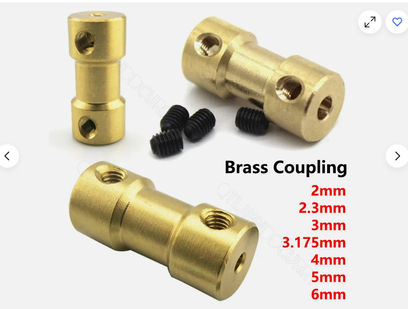
Brass Coupling Motor Shaft Coupling For RC Boat Model DIY 2mm 3mm 4mm 5mm 6mm
You will need this size: 3mm(or 3.175mm) to 5mm
Hello Kevman,
i bought it from ebay:
Brass Coupling Motor Shaft Coupling For RC Boat Model DIY 2mm 3mm 4mm 5mm 6mm
You will need this size: 3mm(or 3.175mm) to 5mm
Uploaded files:Quote from romanvaluiskih@gmail.com on November 2, 2024, 5:20 pmQuote from romanvaluiskih@gmail.com on October 29, 2024, 10:43 pmHello! I started to assembly today. Mostly done in one Day. Need to reprint few parts and would like to remake Front shock mount for using bought shocks. Need to be taller and ofsetted to fit shock properly. Also have to remake lower arms to fit turnbuckles and drive shaft parts to make a bit bigger suspension travel
Well, i remade front suspension mount and today found out, that in 3rd release it is already made 😀 i used rear shock part, which added to front mount piece , same 50mm xD. Also i made rear turnbuckle longer, so i could use 20mm bolt threaded part.
Would offer bit different steering part design, somehow my balljoint falls off everytime. Maybe make steering rod ends look downward to simlify wishbone construction? Will try on 3rd vesion doing that. I wish i had more experience in that, so id make direct steering, placing servo in the middle of the frame and moving bar with bolt (steering bar will have this () type hole and bolt head will push the bar, sliding in that “()” ) sorry for my english 😀
Quote from romanvaluiskih@gmail.com on October 29, 2024, 10:43 pmHello! I started to assembly today. Mostly done in one Day. Need to reprint few parts and would like to remake Front shock mount for using bought shocks. Need to be taller and ofsetted to fit shock properly. Also have to remake lower arms to fit turnbuckles and drive shaft parts to make a bit bigger suspension travel
Well, i remade front suspension mount and today found out, that in 3rd release it is already made 😀 i used rear shock part, which added to front mount piece , same 50mm xD. Also i made rear turnbuckle longer, so i could use 20mm bolt threaded part.
Would offer bit different steering part design, somehow my balljoint falls off everytime. Maybe make steering rod ends look downward to simlify wishbone construction? Will try on 3rd vesion doing that. I wish i had more experience in that, so id make direct steering, placing servo in the middle of the frame and moving bar with bolt (steering bar will have this () type hole and bolt head will push the bar, sliding in that “()” ) sorry for my english 😀
Quote from kevman1 on November 2, 2024, 9:51 pmwhat is the difference betwen v2.0- rockin arms and the orginal ? they both look the same to me in the slicer.
what is the difference betwen v2.0- rockin arms and the orginal ? they both look the same to me in the slicer.
Quote from antibala on November 4, 2024, 8:26 amThe original version couldn’t print without support, while the new one can print without it.
The original version couldn’t print without support, while the new one can print without it.
Quote from kevman1 on November 4, 2024, 4:14 pmQuote from Kelpik on August 22, 2024, 1:20 amTime to to print it again… Had to remake the whole thing because i found too many problems with the fitment. And Fusion just wasn’t cooperating, there were just too many triangles and everything had weird dimensions. I remade the gearbox housing from scratch. In the file there is a set of gears below the gearbox which i will test to see if they work better in this gearbox.
Here is the file with the gearbox in the 3mf format:
https://www.mediafire.com/file/w1e9nb712hqcjzh/Open_Differential_v6.3mf/file
I tried this out, love the design, but unfortunately I had a couple of issues. First the main gear, the parts that stick up super thin and I easily broke them during the assembly. The second, it doesn’t run smoothly for me , I assume due to the bearings and housing being printed material it doesnt slide well. I think lube would fix that issue but aside from that the main gear is the issue.
Quote from Kelpik on August 22, 2024, 1:20 amTime to to print it again… Had to remake the whole thing because i found too many problems with the fitment. And Fusion just wasn’t cooperating, there were just too many triangles and everything had weird dimensions. I remade the gearbox housing from scratch. In the file there is a set of gears below the gearbox which i will test to see if they work better in this gearbox.
Here is the file with the gearbox in the 3mf format:
https://www.mediafire.com/file/w1e9nb712hqcjzh/Open_Differential_v6.3mf/file
I tried this out, love the design, but unfortunately I had a couple of issues. First the main gear, the parts that stick up super thin and I easily broke them during the assembly. The second, it doesn’t run smoothly for me , I assume due to the bearings and housing being printed material it doesnt slide well. I think lube would fix that issue but aside from that the main gear is the issue.
Quote from kevman1 on November 5, 2024, 1:19 pmHi – I have a need for a 308mm wheelbase. Is there an easy way to achieve this by “stacking” parts ?
Hi – I have a need for a 308mm wheelbase. Is there an easy way to achieve this by “stacking” parts ?
Quote from romanvaluiskih@gmail.com on November 6, 2024, 12:42 pmQuote from romanvaluiskih@gmail.com on November 2, 2024, 5:20 pmQuote from romanvaluiskih@gmail.com on October 29, 2024, 10:43 pmHello! I started to assembly today. Mostly done in one Day. Need to reprint few parts and would like to remake Front shock mount for using bought shocks. Need to be taller and ofsetted to fit shock properly. Also have to remake lower arms to fit turnbuckles and drive shaft parts to make a bit bigger suspension travel
Well, i remade front suspension mount and today found out, that in 3rd release it is already made 😀 i used rear shock part, which added to front mount piece , same 50mm xD. Also i made rear turnbuckle longer, so i could use 20mm bolt threaded part.
Would offer bit different steering part design, somehow my balljoint falls off everytime. Maybe make steering rod ends look downward to simlify wishbone construction? Will try on 3rd vesion doing that. I wish i had more experience in that, so id make direct steering, placing servo in the middle of the frame and moving bar with bolt (steering bar will have this () type hole and bolt head will push the bar, sliding in that “()” ) sorry for my english 😀
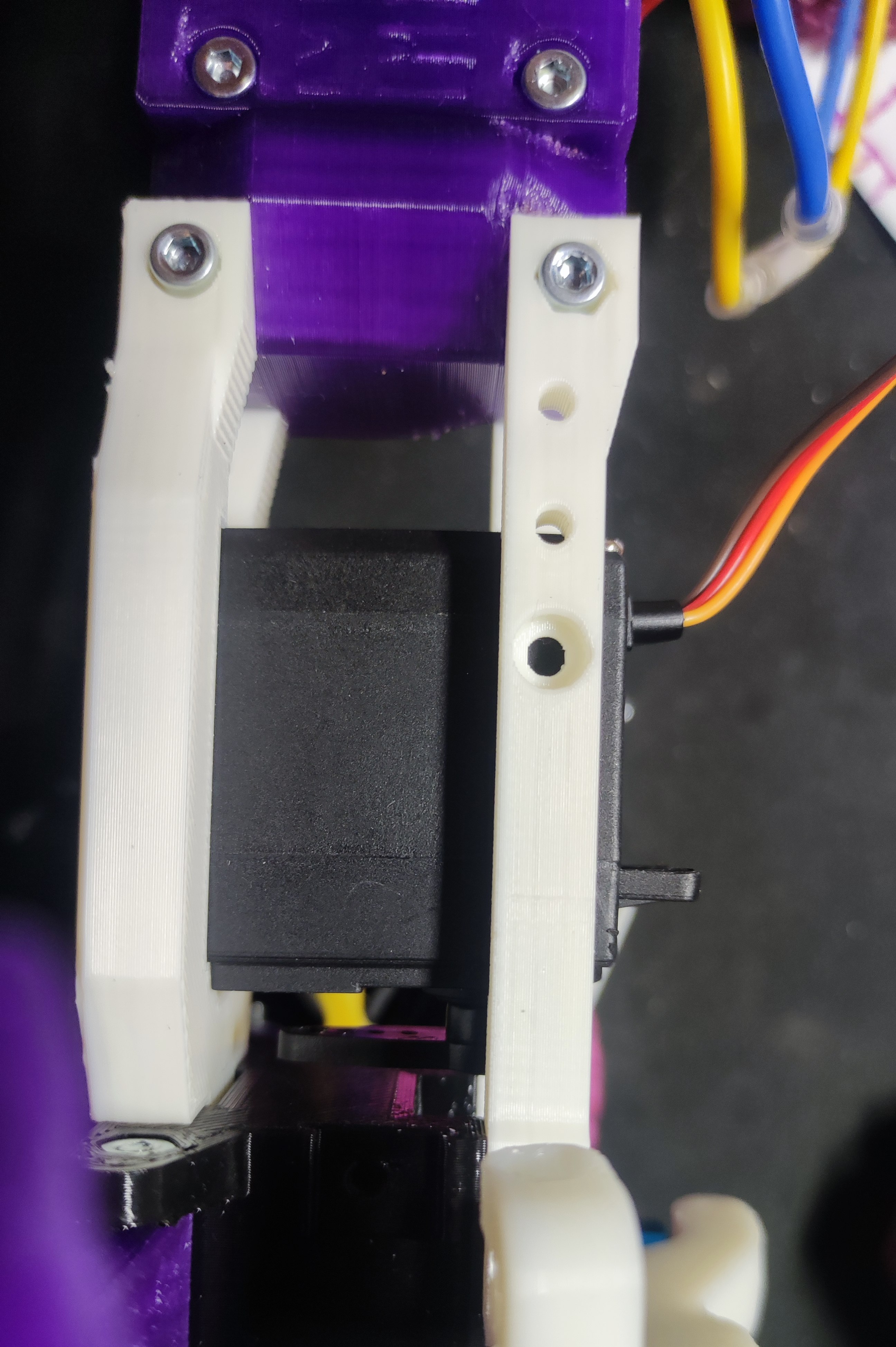
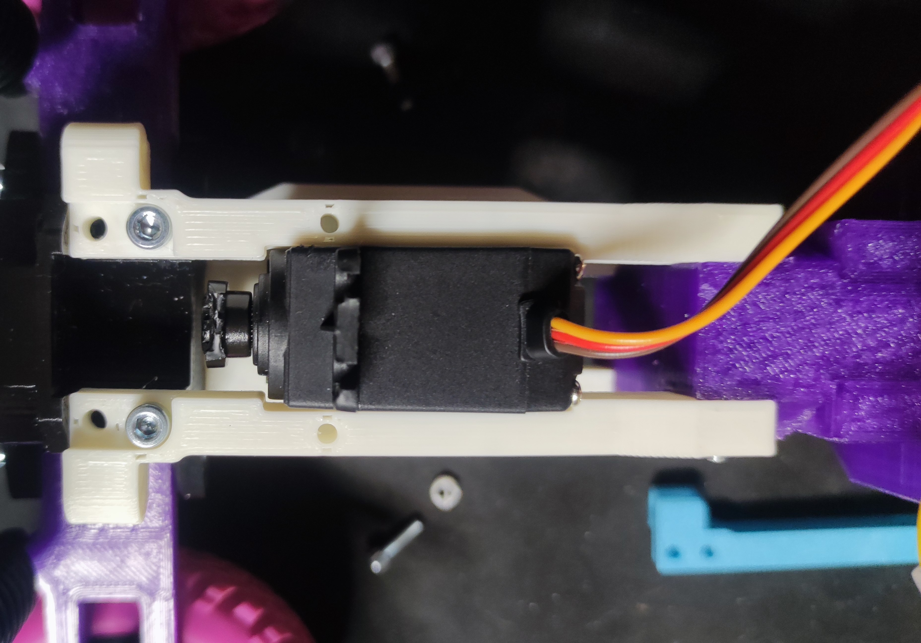
Made some amateur prototyping for direct steering. Now need to make pulling arms and rocker
Quote from romanvaluiskih@gmail.com on November 2, 2024, 5:20 pmQuote from romanvaluiskih@gmail.com on October 29, 2024, 10:43 pmHello! I started to assembly today. Mostly done in one Day. Need to reprint few parts and would like to remake Front shock mount for using bought shocks. Need to be taller and ofsetted to fit shock properly. Also have to remake lower arms to fit turnbuckles and drive shaft parts to make a bit bigger suspension travel
Well, i remade front suspension mount and today found out, that in 3rd release it is already made 😀 i used rear shock part, which added to front mount piece , same 50mm xD. Also i made rear turnbuckle longer, so i could use 20mm bolt threaded part.
Would offer bit different steering part design, somehow my balljoint falls off everytime. Maybe make steering rod ends look downward to simlify wishbone construction? Will try on 3rd vesion doing that. I wish i had more experience in that, so id make direct steering, placing servo in the middle of the frame and moving bar with bolt (steering bar will have this () type hole and bolt head will push the bar, sliding in that “()” ) sorry for my english 😀
Made some amateur prototyping for direct steering. Now need to make pulling arms and rocker
Uploaded files:Quote from kevman1 on November 6, 2024, 3:36 pmQuote from romanvaluiskih@gmail.com on November 6, 2024, 12:42 pmQuote from romanvaluiskih@gmail.com on November 2, 2024, 5:20 pmQuote from romanvaluiskih@gmail.com on October 29, 2024, 10:43 pmHello! I started to assembly today. Mostly done in one Day. Need to reprint few parts and would like to remake Front shock mount for using bought shocks. Need to be taller and ofsetted to fit shock properly. Also have to remake lower arms to fit turnbuckles and drive shaft parts to make a bit bigger suspension travel
Well, i remade front suspension mount and today found out, that in 3rd release it is already made
i used rear shock part, which added to front mount piece , same 50mm xD. Also i made rear turnbuckle longer, so i could use 20mm bolt threaded part.
Would offer bit different steering part design, somehow my balljoint falls off everytime. Maybe make steering rod ends look downward to simlify wishbone construction? Will try on 3rd vesion doing that. I wish i had more experience in that, so id make direct steering, placing servo in the middle of the frame and moving bar with bolt (steering bar will have this () type hole and bolt head will push the bar, sliding in that “()” ) sorry for my english
Made some amateur prototyping for direct steering. Now need to make pulling arms and rocker
Very nice! I look forward to seeing the end result!
Quote from romanvaluiskih@gmail.com on November 6, 2024, 12:42 pmQuote from romanvaluiskih@gmail.com on November 2, 2024, 5:20 pmQuote from romanvaluiskih@gmail.com on October 29, 2024, 10:43 pmHello! I started to assembly today. Mostly done in one Day. Need to reprint few parts and would like to remake Front shock mount for using bought shocks. Need to be taller and ofsetted to fit shock properly. Also have to remake lower arms to fit turnbuckles and drive shaft parts to make a bit bigger suspension travel
Well, i remade front suspension mount and today found out, that in 3rd release it is already made
i used rear shock part, which added to front mount piece , same 50mm xD. Also i made rear turnbuckle longer, so i could use 20mm bolt threaded part.
Would offer bit different steering part design, somehow my balljoint falls off everytime. Maybe make steering rod ends look downward to simlify wishbone construction? Will try on 3rd vesion doing that. I wish i had more experience in that, so id make direct steering, placing servo in the middle of the frame and moving bar with bolt (steering bar will have this () type hole and bolt head will push the bar, sliding in that “()” ) sorry for my english
Made some amateur prototyping for direct steering. Now need to make pulling arms and rocker
Very nice! I look forward to seeing the end result!
Quote from kevman1 on November 7, 2024, 1:02 amI was able to create a mount for my printed bodies yay! Also made a custome middle bracket for a 308 wheelbase
https://ibb.co/vvts9Lr
https://ibb.co/WkJY90V
https://ibb.co/Twjv2j6
I was able to create a mount for my printed bodies yay! Also made a custome middle bracket for a 308 wheelbase
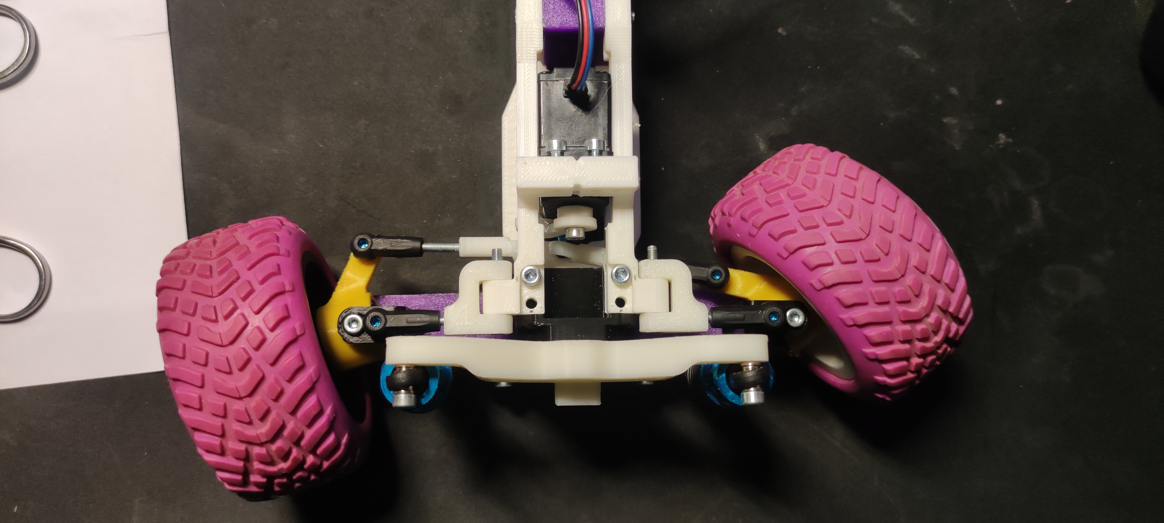
Quote from romanvaluiskih@gmail.com on November 10, 2024, 8:32 pmWell, i can say, that my version of servo steering is ready. Add my files too to improve project, maybe someone want to make this type of steering.
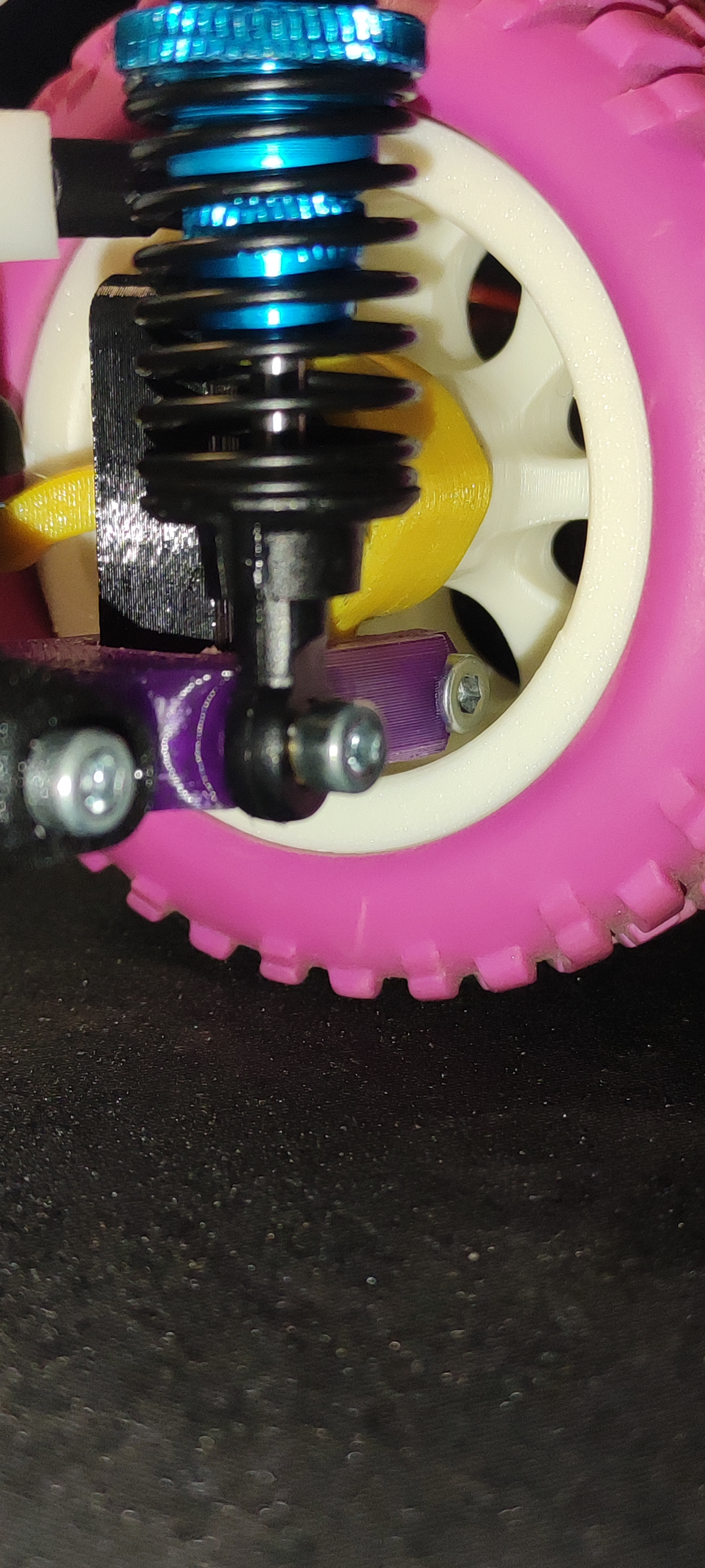
I also made wheels, so it can be more offroady (tires from daughters toy 😁clearances came out good
maybe need to remake servo part later to make steering wider.
Cant upload stl files, so if anyone wants, can give link to admin, so he could add it to new version
Well, i can say, that my version of servo steering is ready. Add my files too to improve project, maybe someone want to make this type of steering.
I also made wheels, so it can be more offroady (tires from daughters toy 😁clearances came out good
maybe need to remake servo part later to make steering wider.
Cant upload stl files, so if anyone wants, can give link to admin, so he could add it to new version
Uploaded files:
Quote from antibala on November 11, 2024, 9:00 amHello Roman,
i like the steering you made, thanks for sharing it to us !
My bro will answer about how to upload the stls.
Best regards
Balázs
Hello Roman,
i like the steering you made, thanks for sharing it to us !
My bro will answer about how to upload the stls.
Best regards
Balázs
Quote from Szilard on November 11, 2024, 9:50 amHey Guys,
I am very soon gonna create a safe way to share your upgrades/versions! Unfortunately, creating a system which is safe for everyone is much trickier than you just first think of it. Please give me some time, hopefully will be ready in November!
Hey Guys,
I am very soon gonna create a safe way to share your upgrades/versions! Unfortunately, creating a system which is safe for everyone is much trickier than you just first think of it. Please give me some time, hopefully will be ready in November!
Quote from kevman1 on November 13, 2024, 5:55 pmCan you provide links to good springs and or shocks you are able to use. MY bodies are heavy and tend to bottom out with some of the springs and shocks I have.
Can you provide links to good springs and or shocks you are able to use. MY bodies are heavy and tend to bottom out with some of the springs and shocks I have.
Quote from Szilard on November 17, 2024, 10:29 amHi Kev,
we always buy them from the local shop or from ebay. I would really say if they were special, but they are the most common ones on the market. Recently, we were looking for lighter springs (as our bodies were light), we were successful in the RC shop not far from us. Maybe in the product description there is a note that it is a “stronger” spring? (just guessing)
Really dont know Kev, good luck finding the right ones!!
Hi Kev,
we always buy them from the local shop or from ebay. I would really say if they were special, but they are the most common ones on the market. Recently, we were looking for lighter springs (as our bodies were light), we were successful in the RC shop not far from us. Maybe in the product description there is a note that it is a “stronger” spring? (just guessing)
Really dont know Kev, good luck finding the right ones!!
Quote from kevman1 on November 19, 2024, 3:24 pmHi – new problem, I seem to be stripping the Servo arm often. Any ideas on how to make that steering work with the servo arms that come with the servo? They seems to have more “teeth” from the injection molding process.
Hi – new problem, I seem to be stripping the Servo arm often. Any ideas on how to make that steering work with the servo arms that come with the servo? They seems to have more “teeth” from the injection molding process.
Quote from antibala on November 20, 2024, 7:50 amHello Kevman,
Did you secure the arm to the servo wit h screw? I’ve never encountered this issue after tightening it.
You could try printing the arm in ABS instead of PLA. ABS has a higher shrinkage rate, which might make it fit more tightly and securely onto the servo head.
Alternatively, you can try reducing the scale of the part by 1% (so it’s 99% of its original size) to see if that helps.
Hello Kevman,
Did you secure the arm to the servo wit h screw? I’ve never encountered this issue after tightening it.
You could try printing the arm in ABS instead of PLA. ABS has a higher shrinkage rate, which might make it fit more tightly and securely onto the servo head.
Alternatively, you can try reducing the scale of the part by 1% (so it’s 99% of its original size) to see if that helps.
Quote from kevman1 on November 21, 2024, 3:15 amYes I did use the screws to secure the arm. I also printed in in PC blend and annealled the part as well. I will try scaling it down by 1% and see if that works
Thank you!
Yes I did use the screws to secure the arm. I also printed in in PC blend and annealled the part as well. I will try scaling it down by 1% and see if that works
Thank you!
Quote from kevman1 on November 21, 2024, 3:35 amI finally got my 69 roadrunner mounted to this great chassis. I have to tweak a couple of things, since the wheels in the back are wider, I have to go a little less than 190mm rear track, easy to do since we have so many options with this chassis. I also need to figure out shocks that provide and adequate amount of sag so that it does not sit to high. Love it! I was drifting this thing around the other day. I still need to work on my custom ESC / Receiver /Battery strap as it is a bit too high.
https://ibb.co/8KcyLy2
https://ibb.co/H7PgfXZ
https://ibb.co/GkmC6XT
https://ibb.co/ccYt3Kj
I finally got my 69 roadrunner mounted to this great chassis. I have to tweak a couple of things, since the wheels in the back are wider, I have to go a little less than 190mm rear track, easy to do since we have so many options with this chassis. I also need to figure out shocks that provide and adequate amount of sag so that it does not sit to high. Love it! I was drifting this thing around the other day. I still need to work on my custom ESC / Receiver /Battery strap as it is a bit too high.
Quote from antibala on November 21, 2024, 11:59 amThanks for the pictures, they look awesome! 😀
I really like the modifications you made to fit this body to the chassis; it’s truly inspiring!
Thanks for the pictures, they look awesome! 😀
I really like the modifications you made to fit this body to the chassis; it’s truly inspiring!
Did you know??? You can set your profile image in My Account/Profile&Membeship/Edit Profile!
